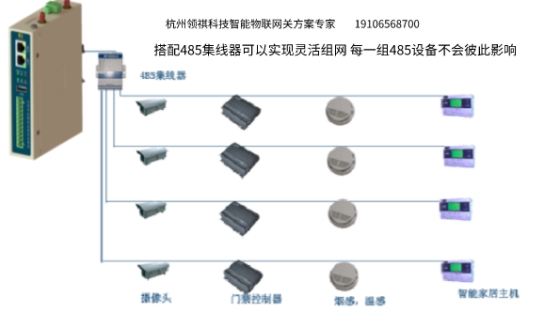
It is recommended that no more than 32 devices be connected through one 485 serial port. In the unattended scenario, it is recommended that both active and standby devices be purchased (the same device is allocated to the 485 chain of different serial ports for collection respectively), so as to reduce the cost of fault intervention and later maintenance of manual inspection as much as possible. For industrial control application scenarios with high communication requirements, photoelectric isolation 485 module can be configured to avoid the failure of the entire 485 chain caused by a device fault in series. After the photoelectric isolation module is configured, the 485 network is more flexible. It can flexibly adapt the water and electricity meters distributed between floors to the same gateway device for centralized control and forwarding.
Hangzhou Lingqi Internet of Things gateway has at least one serial port and at most 16 serial ports. Maximum number of supported devices 16 x 32=512 simple smart devices.
In addition, the gateway equipment links PLC CNC inverter with complex point table equipment, need to consider the processing capacity of the equipment, storage performance, etc. Depending on the type of gateway, there will also be limitations. Hangzhou Lingqi intelligent gateway supports 800 to 100,000 data collection points, covering the data collection needs of most industrial application environments.
How to connect multiple RS485 devices?
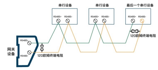
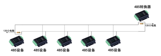
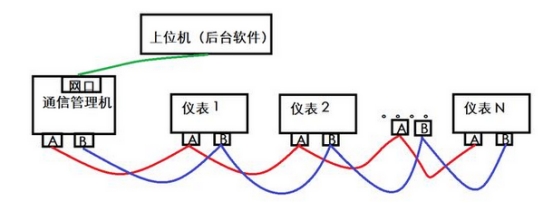
A shielded twisted pair cable is used to connect the gateway to each serial device node in a hand-to-hand Daisy chain topology. A 120Ω resistor is connected to the RS485+ and RS485- of the device at the beginning and end of the network to reduce signal reflection at both ends.
When do I need to increase terminal resistance on the RS485 bus?
The RS485 bus will generate echo reflection signals with the extension of the transmission distance. In order to avoid signal reflection, resulting in unstable signal transmission, when the cable length is long (such as more than 100 meters), the data transmission line must have the end point, and the branch length as short as possible. The correct terminal requires a match of terminal resistance RT, whose value is the characteristic impedance of the transmission line Z0. Z0 of standard RS-485 cables is 120 ohms. The end of a cable trunk usually matches a resistance of 120Ω, one at the beginning and one at the end of the cable.
How many devices can the RS485 bus be connected to?
The number of RS485 devices that can be connected to a bus depends on the load capacity of the RS485 converters of these devices. General RS485 chip load capacity has three levels of 32, 128 and 256 sets. The typical RS485 device has a load capacity of 32 units.
What is the maximum transmission distance in RS485 communication?
Theoretically, the relay communication distance of RS485 bus is 1200M, but this is only the theoretical structure of RS485 bus and only in an ideal environment. Communication wire quality standard, baud rate 9600bps, only one RS485 equipment can make the communication distance to reach 1200 meters, and can communicate does not mean that each communication is normal, usually the actual stable communication distance of RS485 bus far less than 1200 meters.
Load equipment, wire impedance is not up to standard, wire diameter is too fine, converter quality is poor, equipment lightning protection, baud rate increase and other factors will reduce the communication distance.
If the bus extension distance exceeds 1000 m, you need to use an RS485 bus repeater.
Some measures to ensure the quality of communication:
1. Common ground method: Connect the GND ground of all 485 devices with one wire or shielded wire to avoid potential difference between all devices that may affect communication.
2, terminal resistance method: in the last 485 equipment 485+ and 485- on the parallel connection of 120 ohm terminal resistance to improve the quality of communication.
3. If the communication distance is too long, it is suggested to use a repeater or 485HUB to solve the problem if it exceeds 500 meters. If there is too much load, it is recommended to use 485HUB if there are more than 30 on a bus to solve the problem.
When high data rates are used, only short cables can be used. If you use a low data rate, you can use a longer cable. For low-rate applications, the cable's DC resistance increases the noise margin by increasing the cable voltage drop and limiting the cable length. With high rate applications, the AC effect of the cable limits signal quality and cable length.
What does the Massage Delimiter parameter mean when setting serial communication transmission parameters?
Because there is no start bit and stop bit in Modbus data frame, so it is not possible to distinguish two frames of data by specific data, need to be distinguished by time interval, Massage Delimiter means interval time, such as the protocol stipulates that the information frame should be sent with at least 3. 5 characters pause interval. That is, after the transmission of the last character of a data frame is completed, a pause of at least 3.5 characters is required to mark the end of the data frame, and a new data frame can start after this pause. If a new message starts with the previous message in less than 3.5 characters, the receiving device considers it to be a continuation of the previous frame, which results in a CRC check error. And the entire data frame must be transmitted as a continuous stream. If there is a pause time of more than 1.5 characters before frame completion, the receiving device will refresh the incomplete data frame and consider packet loss.
A character consists of a 1bit start bit, 8bit data bit, 1bit parity bit, and 1bit stop bit.
Update time, Timeout time, Retry times, and ReConnection time for each Modbus instruction. What is the relationship between them?
Update time is the update time of request instruction. After the master Modbus sends request data, if it does not receive response data from the slave device within Timeout time, the master Modbus will continue to send request data. If it does not receive response data from the device after consecutive Retry times, The master station considers that the slave device is disconnected and does not send request packets to the slave device before ReConnection time. Otherwise, the bus polling time is increased.


 0086-18958100293